Wireshark dump
There’s a lot of info in the Wireshark dump, so the first thing to do is to filter the address to my IP cam’s IP so we only see what it sends/receives.
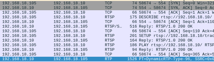
We can see there’s some sort of ping-pong going on at first.
sequenceDiagram
participant c as Client
participant s as IP Cam (Server)

c->>s: DESCRIBE
s->>c: Reply

c->>s: SETUP
s->>c: Reply

c->>s: PLAY
s->>c: Reply

s-->>c: Video Data
The protocol tab of wireshark informs us that this comms is RTSP 1.0.
Note: This capture was done by running the retina crate, which is what I’m contributing to. It only supports
RTSP 1.0which is why we’re going to be looking at RFC 2326, not RFC 7826 which isRTSP 2.0.
Looking at RTSP comms
DESCRIBE
Nothing too special about this packet except the fact that we’re asking to receive the content in application/sdp.
SETUP
Interesting to note that retina has hard-coded the Transport option as
RTP/AVP/TCP;unicast;interleaved={proposed_channel_id}-{proposed_channel_id + 1}
PLAY
The interesting part here is sending npt=0.000-, which I guess means start playing video immediately (0.000) & continuously (-).
Analyzing the first RTP payload
Once the camera replies to the PLAY request, it starts sending out video data i.e. H.264 inside RTP packets. We can now filter wireshark capture by setting ip.src_host == {camera_ip} so we see one-way comms from IP camera to my system, and inspect the RTP payload.
H.264 video in RTP packets
We can use RFC 6184 to understand what the payload of the RTP packets will be.
From Section 5.2:
A receiver can identify the payload structure by the first byte of the RTP packet payload
and also,
This byte is always structured as a NAL unit header. The NAL unit type field indicates which structure is present.
The first byte of the RTP payload will tell us what type of payload structure it is. Read Section 5.2 to understand the three types of payload structures.
RTP payload
Here’s the first few bytes
0000   3c 87 4d 00 1f e7 40 28 02 dd 80 a5 05 05 05 f0
0010   00 00 03 00 10 00 00 03 02 8b 01 00 02 dc 68 00
0020   02 25 51 7f ff 02 80 00 00 00 01 28 ee 3c 80 00
0030   00 00 01 25 b8 40 00 10 5b fc 84 a5 08 ec d2 43
0040   b6 58 0b ec 17 2e 74 65 73 80 73 90 8b d5 7a f5
0050   9e ea 8c 8e 55 09 80 cf 50 19 4b 8a 08 ac 2f 3c
First byte of RTP payload
As mentioned in the RFC, we’ll analyze the first byte (0x00) which is 3c.
3c in binary is 00111100.
The RFC told us that this is always structured as a NAL unit header, which is defined in Section 1.3 as:
+---------------+
|0|1|2|3|4|5|6|7|
+-+-+-+-+-+-+-+-+
|F|NRI|  Type   |
+---------------+
The first byte represented as a NAL unit header.
+---------------+
|0|0|1|1|1|1|0|0|
+-+-+-+-+-+-+-+-+
|F|NRI|  Type   |
+---------------+
Payload structure identification
We’re interested in the Type value, which is 11100. This in decimal is 28, which is, acc. to Table 1 of Section 5.2, a FU-A packet.
Second byte of RTP payload
Now we know that the first RTP packet is of type FU-A, we can look at its doc to move forward. The format is defined in Figure 14 as:
0                   1                   2                   3
0 1 2 3 4 5 6 7 8 9 0 1 2 3 4 5 6 7 8 9 0 1 2 3 4 5 6 7 8 9 0 1
+-+-+-+-+-+-+-+-+-+-+-+-+-+-+-+-+-+-+-+-+-+-+-+-+-+-+-+-+-+-+-+-+
| FU indicator  |   FU header   |                               |
+-+-+-+-+-+-+-+-+-+-+-+-+-+-+-+-+                               |
|                                                               |
|                         FU payload                            |
|                                                               |
|                               +-+-+-+-+-+-+-+-+-+-+-+-+-+-+-+-+
|                               :...OPTIONAL RTP padding        |
+-+-+-+-+-+-+-+-+-+-+-+-+-+-+-+-+-+-+-+-+-+-+-+-+-+-+-+-+-+-+-+-+
One key point of FU-A packets:
Fragmentation is defined only for a single NAL unit and not for any aggregation packets.
Meaning a FU-A packet (which can consist of multiple packets i.e. fragmented) can contain data of only a single NAL unit, not multiple.
^ Remember that.
Now, we’ve already read the first byte, which is the FU indicator, let’s read the second byte i.e. FU header.
The second byte (0x01) is 87, which in binary is 10000111.
Format of FU header:
+---------------+
|0|1|2|3|4|5|6|7|
+-+-+-+-+-+-+-+-+
|S|E|R|  Type   |
+---------------+

S (start bit)
E (end bit)
R (reserved bit)
Type (NALU payload type) <-- interest
Our second byte as FU header is:
+---------------+
|1|0|0|0|0|1|1|1|
+-+-+-+-+-+-+-+-+
|S|E|R|  Type   |
+---------------+
Since it is the first fragment of FU-A, the start bit is 1, and the NAL payload type is 00111, which in decimal is 7.
The NAL unit type of 7 is for SPS.
Now we know the following:
- The packet is a FU-A packet
- The FU-A packet has the header of SPS, meaning the data after FU header is supposed to be entirely for SPS
Let’s start reading the packet further.
Reading next bytes
Emulation Prevention Bytes (EPBs)
There are emulation prevention bytes (EPBs) at byte 0x12 and 0x17.
Start code
There is a start code at 0x27 till 0x2a i.e. 0x00_00_00_01.
Next NALU (PPS header & data)
At 0x2b, we get the header of next NALU 0x28, or 00101000, where type of NALU is 01000, which is 8 i.e. PPS. Subsequent bytes are PPS data.
Start code
There is a start code at 0x2f till 0x32 i.e. 0x00_00_00_01.
Next NALU header (IDR header & data)
At 0x33 is next NALU header 25, or 00100101, where type of NALU is 00101, which is 5 for IDR. Subsequent bytes are IDR data.
How FU-As should be
Notice that the FU-A packets are fragmented. And remember when I quoted the RFC which explicitly said that:
Fragmentation is defined only for a single NAL unit and not for any aggregation packets.
This means that when we have received a FU-A packet i.e. we receive all fragmented packets for that FU-A, starting from the first packet with start bit set to 1, until the final packet with end bit set to 1, will be of a single NALU.
FU-A example

[3c 87 ...] # first fragmented packet of FU-A
[3c 07 ...], [3c 07 ..], .. , [3c 07] # middle fragmented packets
[3c 47 ...] # last fragmented packet of FU-A
The payload of the entire FU-A packet should be of a single NALU, which is made clear by the last digit in second byte 7, meaning these packets were for SPS.
What our FU-A is
So we know what the payload of the FU-A should be, i.e. data for SPS.
However
We’ve received an Annex B stream in the FU-A packet, which contains SPS, PPS and IDR slice.
Normally, IDR slices are big so they’re commonly sent over FU-A packets, but my camera is bundling up SPS & PPS with the IDR slice into an Annex B stream, and sending that through FU-A, which acc. to the RFC, ain’t what we was supposed to do dawg.
This is essentially what we’re receiving.
[
3c           # FU-A
87           # start of FU-A for SPS
..           # SPS data
(start code) # end of last NALU
28           # single NALU for PPS
..           # PPS data
(start code) # end of last NALU
25           # single NALU for IDR
..           # IDR data
]

[
3c           # FU-A
07           # middle packets of FU-A for SPS
..           # IDR data
]

[
3c           # FU-A
47           # end of FU-A for SPS
..           # IDR data
]
Funny how the FU-A fragments after the first one still say that they’ll have SPS, but they instead have IDR slice since that’s the last NALU in the Annex B stream.
Conclusion
The camera is not conforming to the RFC, which is why retina isn’t able to work. I’ll need to come up with a solution for parsing the Annex B stream in FU-A packets so retina works with my camera.
Spoiler alert: I did make a PR before but the code didn’t feel good, which is why I’m gonna attempt doing it again.
Update: Opened up a PR for adding support for my camera.